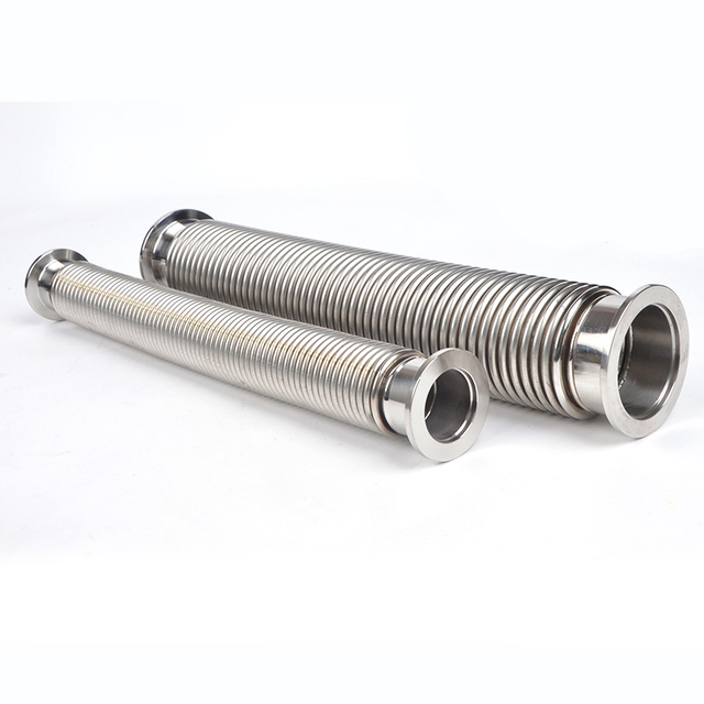
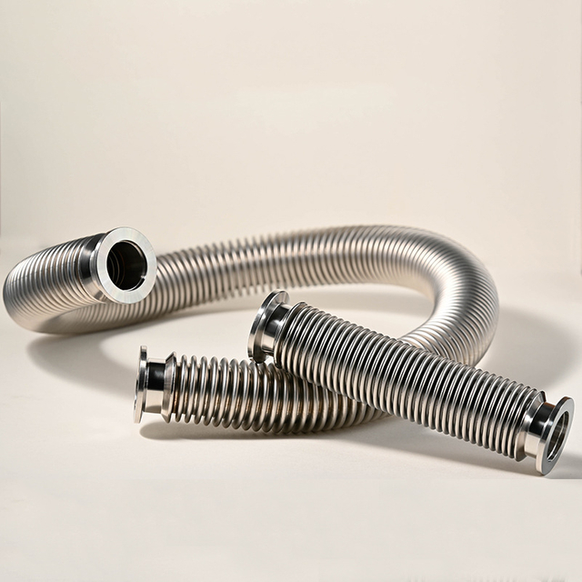
Suppose you need to replace the flexible line between a pump and a chamber. The new hose has the same bore as the old one, but its clamp fouls the pump housing. Adding an adapter at the chamber end would also leave too little room for the hose. Both problems can be caught on the drawing. Start by identifying the vacuum flanges at the two ports, then check how each joint seals and how much room it needs. Once the ends are settled, you can choose the fittings and work out how much space is left for the bellows.
Vacuum Flanges at a Glance: KF, CF, ISO-K and ISO-F
Start with the flange face and the hardware that holds it in place. A quick clamp around a beveled rim points to KF. Bolt holes narrow the possibilities, but you still need to look at the seal seat. A CF knife edge and an ISO centering seal work differently, even when the two flanges look similar from the back.
| Family | Recognition and sealing | Fastening and access | What to verify on the drawing |
|---|---|---|---|
| KF / NW | Bevel behind the flange rim. A centering ring locates an elastomer O-ring. | A circumferential quick clamp engages both rims. Allow space to open the clamp. | Nominal size, flange and seal seat dimensions, clamp fit. |
| CF | Recessed knife edge around the bore and a soft metal gasket, commonly copper. | Bolts load the joint. Plan for tool access and a new gasket when reopening it. | Flange OD, bolt circle, hole count and type, gasket dimensions. |
| ISO-K | Clamp engagement at the rim and a centering seal assembly. | Claw clamps secure a typical ISO-K pair. Check clearance around the rim. | Nominal DN, seal seat, rim profile and required clamp arrangement. |
| ISO-F | Flange with a bolt pattern and a centering seal assembly. | Bolts secure the joint. Check both the pattern and access behind the flange. | Nominal DN, bolt circle, hole count, fasteners and mating face. |
For a replacement line, the pump and chamber ports usually make the first decision for you. Photograph both faces before comparing parts, especially if a previous installation already used an adapter. If you are laying out a new line, think about how often you will open the joints and whether you will still be able to reach the hardware once the equipment is in place.
KF Vacuum Flanges: Clamps, Centering Rings and Seals
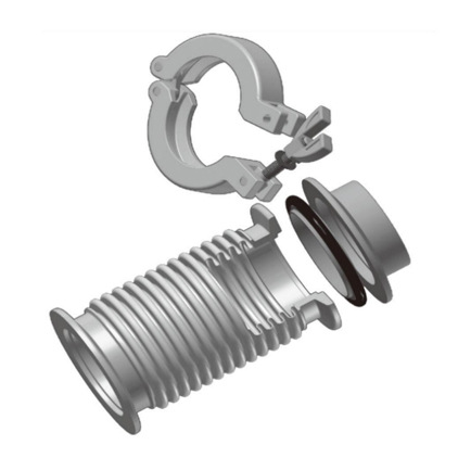
A KF vacuum flange is easy to recognize once you see the three parts together. The centering ring sits between the two flange faces and holds the O-ring in position. The quick clamp wraps around the beveled rims and draws the flanges together. If you are replacing just the ring or clamp, check it against the flange you already have. Matching the nominal size is the starting point for that check.
One example is Yueding’s KF16/NW16 stainless steel flexible hose. KF16 and NW16 identify the same nominal interface in this product name. If you are replacing a hose on an existing KF16 line, check the flange at the other end too, then measure the required face-to-face length. Yueding’s KF vacuum bellows hoses can be paired with matching clamps and centering rings. List those parts on the order if you need them with the hose.
Choose the seal for the conditions at the joint
If you keep spare O-rings, record their material and size so they can be matched to the joint. If the line is exposed to a cleaning chemical or goes through bakeout, check the seal against those conditions. On a joint that opens frequently, follow the equipment’s maintenance instructions when deciding whether to reuse a seal or fit a new one.
CF Vacuum Flanges: Knife Edges and Metal Gaskets
Look inside the bolt circle on a CF vacuum flange and you will see the knife edge around the bore. Tightening the bolts presses the two knife edges into a soft metal gasket, commonly copper. This is why a flange can have the correct hole pattern and still be unsuitable for reuse if the sealing edge is damaged.
When you open a CF joint, inspect both knife edges before fitting a fresh gasket. Look for damage or debris where the edge contacts the gasket. Match the replacement gasket to the flange drawing, including its diameter, thickness and material, and follow the installation instructions for the joint.
If you are working from an old parts list, check what its CF size refers to. A flange outside diameter and a nominal bore describe different dimensions. Put the bolt circle, hole count and hole type on the replacement drawing. For an elbow that must point in a particular direction, also check how the bolt holes will line up when the elbow is in position.
ISO Vacuum Flanges: ISO-K vs. ISO-F
An ISO vacuum flange on a larger pump or chamber port may have a clamp rim or a bolt pattern. ISO-K and ISO-F typically use the same kind of centering seal assembly. The difference you will notice at installation is how you reach and tighten the hardware.
| Check | ISO-K | ISO-F |
|---|---|---|
| Fastening | Claws engage the rim of the flange pair. | Bolts pass through or engage the mating bolt pattern. |
| Drawing details | Rim profile, seal seat, and clamp configuration. | Seal seat, bolt circle, hole count, and hole type. |
| Service envelope | Space for clamp bodies and tools around the rim. | Space for bolt insertion, tool access, and withdrawal. |
If the pump has an ISO-K port and the line ends in ISO-F, compare the mating drawings before adding an adapter. Some combinations can be joined with hardware specified for a mixed joint, such as a suitable collar arrangement or purpose-made clamps. The equipment maker’s instructions should identify the hardware and seal arrangement for that connection.
Picture the next time you have to open the joint. On ISO-K, can you reach the claws around the rim? On ISO-F, can you withdraw the bolts without shifting the pump? Checking those clearances on the layout can save a redesign after the line is installed.
Which Vacuum Fittings Do You Need?
Once you know what is on each end, the fitting choice gets simpler. Matching ports need the seal and hardware for that joint. A smaller port may call for a reducer, and a different flange family may call for a transition. If the pump and chamber are close together, sketch the full connection before ordering. A separate adapter uses some of the length you may need for the flexible section.
| Job | Fitting choice | Detail to specify |
|---|---|---|
| Join matching ports | Direct connection with the matching seal and hardware. | Both flange ends and space to fit and remove the fasteners. |
| Change bore | Reducer with the required end sizes. | Clear bore and added length, especially where conductance matters. |
| Change flange family | Transition adapter or bellows with different ends. | Family, size, and sealing kit for each end separately. |
| Close an unused port | Blank flange with the corresponding seal and hardware. | Solid blank, mating face, and clearance for removal. |
| Accommodate movement | Flexible vacuum bellows assembly. | Installed length, allowed movement, and how the assembly is supported. |
Example assembly from a pump port to a chamber port
- Pump flange
Identify family and size. - Joint A
Match seal and fasteners. - Bellows
Specify both end flanges and installed length. - Joint B
Match the chamber seal and fasteners. - Chamber flange
Check the port against End B.
A separate adapter adds length and another joint to assemble. A bellows with different end flanges can be worth considering where space is tight. Either way, label the pump end and chamber end on the drawing. For vacuum equipment bellows, that layout shows where the flexible section sits and which seal and fastener set belongs at each end.

How to Specify Fittings and Vacuum Bellows for a Quote
A marked-up sketch is often enough to start a quote. Label the pump and chamber ends, then show the distance between their mating faces in the installed position. For custom metal bellows, show the direction and amount of movement from that position. If you also know the free length, put it on a separate dimension line so the two lengths are easy to distinguish.
| Field | What to send |
|---|---|
| End A and End B | Family, nominal size, and drawing for each mating port. Include bolt or clamp details and any required orientation. |
| Fittings and hardware | Reducer, adapter, or blank if needed. List the seals, rings, clamps, and bolts to be included at each joint. |
| Installed geometry | Face-to-face length and tolerance, clear bore, maximum outside envelope, and service access. |
| Motion and support | Axial travel, lateral offset, angular movement, whether motions occur together, and expected cycles. Show supports and fixed points. |
| Vacuum and process | Operating and target base pressure with units, process gases, required leak rate and acceptance test if applicable. |
| Temperature and cleaning | Operating range, bakeout temperature and duration, seal material, wetted materials, cleaning and packaging requirements. |
| Maintenance and quantity | Expected disassembly frequency, spare seals, order quantity, and required drawing approval or inspection records. |

If the line will be baked, give the temperature and duration for the whole joint so the bellows, flanges and seals can be reviewed together. For a leak test, say whether the result must cover the bellows alone or the complete assembly. Include the acceptance value, units and test method if your project specifies them.
Final Checks Before Ordering
Before ordering, picture how the finished line will fit between the two ports and how you will open it for service. The vacuum flanges set the connection at each end. The seal, hardware and installed length determine how the pieces come together. If an adapter takes up too much room, mark the available length and ask whether different bellows ends would suit the layout. For a quote from Yueding, include the mating drawings and the movement you expect from the installed bellows. Those details give the manufacturer a clear assembly to review.
Frequently Asked Questions
What photos help identify unmarked vacuum flanges?
Take a straight-on photo of the sealing face and a side view showing the rim and rear clearance. Include the outside diameter, bore, and bolt pattern where present. A photo with a scale helps narrow the options before drawing confirmation.
Why can a reducer affect pumping performance?
A smaller clear bore or a longer flow path can reduce conductance. Check the full path through the fitting, especially if the line has several adapters or a narrow opening near the pump.
Should both end flanges be fixed on a replacement bellows?
Check whether the two ports need a specific bolt-hole orientation. Mark the relative orientation on the drawing if both ends must be fixed. If alignment is uncertain, ask which rotatable options fit the interface and layout.
Can the same bellows handle both axial travel and lateral offset?
Give both movements and say whether they occur at the same time. Ask for the allowable combined movement for the selected assembly at its installed length and operating conditions.
What should be listed separately on the purchase order?
Identify the flange-ended assembly, adapters, seals, and fastening hardware by joint. State which accessories ship with the assembly and which are spares. This makes the delivery easier to check against the installation drawing.