Article Structure Overview
I. Functional Role of Stainless Steel Flex Pipes
II. Installation Position Strategy in Exhaust Systems
III. Structural Engineering Value of Flex Tubes
IV. Bellows vs. Complete Flex Pipe: Design Differences
V. Manufacturing Consistency & Batch Stability
VI. Common Failure Mechanisms in Real Applications
VII. Installation Boundary & Load Constraints
VIII. Engineering Selection Principles for Flexible Exhaust Connections
In real exhaust systems, stainless steel flex pipe is usually not for changing exhaust performance, but is used to deal with a long-existing but often ignored problem, that is the inevitable relative movement between the engine and the exhaust pipe. Because the engine produces periodic vibration continuously during work, and the exhaust pipe will have obvious axial elongation under high temperature condition. If these movements are fully borne by rigid pipes and welds, failures usually concentrate at the muffler joint, flange edge, or near supports. The existence of the flexible section, in essence, is to release these movements within the range allowed by the structure, rather than transferring the problem backwards.
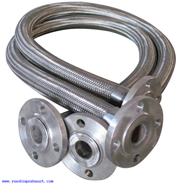
In some multi-exhaust branch or high-performance systems, you will see flexible stainless steel pipe exhaust not only in one place, but multiple sections symmetrically distributed on different exhaust branches. The purpose of this layout is to let each exhaust branch compensate its own dynamic movement individually, not let a single flexible section absorb the complex vibration of the whole system. In practice, this decreases the eccentric loads caused by total movement, and avoids one specific branch failing early under combined high temperature cycles and vibration.
In diesel systems or turbocharged systems, exhaust flex joint is sometimes set in high temperature and high pressure segments (such as after diesel particulate filter or near turbo outlet). In these conditions there are not only engine vibration and thermal elongation, but also exhaust pressure fluctuation, so the flexible components in this area need higher structural capacity and fatigue life. In this high temperature and high pressure environment, flexible tubes with three-layer structure (such as liner + corrugation + braid layer) should be used to meet higher fatigue demands.

Flex tube can provide certain flexibility in axial, lateral and even slight torsion directions, which allows it to absorb engine vibration and the movement caused by thermal expansion of the exhaust system. In contrast, ordinary straight pipes are very rigid; any vibration or thermal movement will be directly transmitted to welds, support points or hangers, easily causing fatigue cracking or hanger deformation.
In addition, the multi-layer structure of flex tube shows better life and stability under pressure and temperature cycling. Straight pipe has almost no buffering ability at high temperature; any thermal elongation must be absorbed by pipe fasteners, otherwise system stress concentrates severely. In engineering, flexible sections not only reduce weld load, but also prolong the service life of the muffler, catalyst, and mid-section pipe.
Moreover, at the installation and maintenance level, flex tube can be matched in limited space, while straight pipe usually requires precise alignment; otherwise, installation can easily cause stress concentration or gas leakage risk. This is also why in the front segment near the engine, mid-segment thermal elongation concentrated area, or multi-exhaust branch system, flexible stainless steel pipe exhaust is more common and necessary than straight pipe.
In summary, the advantage of flex tube is not simply “can bend,” but through flexibility to absorb vibration and thermal expansion, reduce local stress, and extend the overall system life, which is engineering value that straight pipe cannot provide.
Pure bellows structure fully relies on wave body to endure repeated movement, which requires extremely high forming precision and material consistency; while complete flex pipe participates in stress sharing through outer braid and liner structure, which in complex working conditions is easier to maintain shape stability.
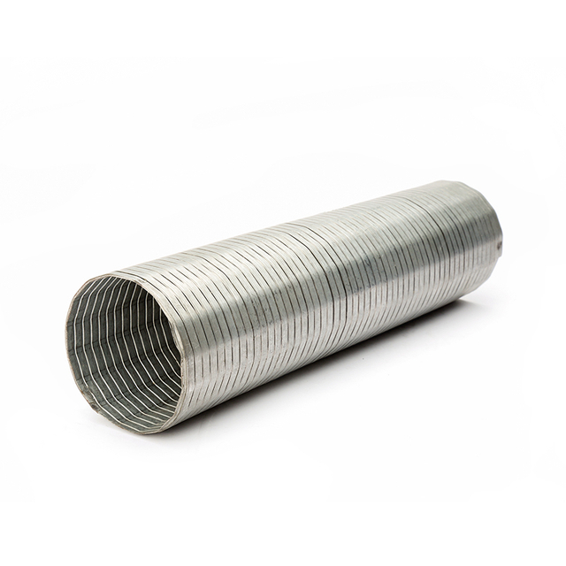
Exhaust bellows is mainly used in exhaust system sections that require absorbing thermal expansion. It usually adopts single-layer or multi-layer corrugated pipe design, which can provide axial extension and contraction ability to alleviate the pipe length change caused by exhaust temperature rise. The flexibility of bellows is mainly concentrated in the axial direction. For absorption of lateral vibration or torsional loads, it is limited, so it is usually installed between rigid pipes in the mid-section or near the muffler and catalyst, to compensate thermal elongation and reduce stress concentration on welds and supports.
In the design and production process, the material choice, corrugation height and thickness of bellows directly determine its extension amount and fatigue life. Larger diameter bellows, if no external support or additional reinforcement, can easily produce local cracks under high temperature and high pressure conditions. In engineering practice, bellows is more used for thermal displacement compensation, not vibration isolation element, and this is the biggest difference between it and flex pipe.
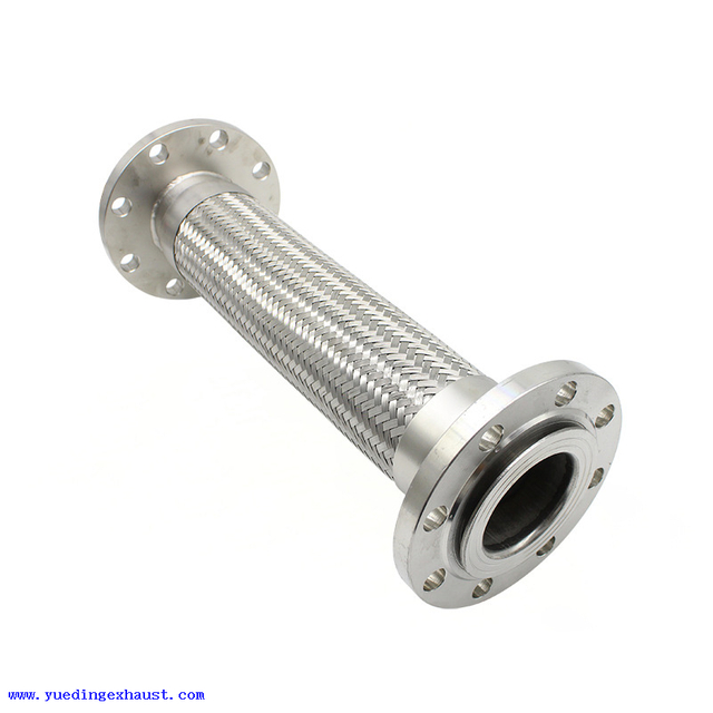
Flex pipe is different. Its structure usually includes corrugated pipe body, outer braided mesh, and when necessary also comes with Interlock liner. Flex pipe’s design not only can absorb axial thermal expansion, but also can buffer lateral vibration and torsional loads, which makes it very suitable to install in the front section near the engine or at the exhaust branch merge area. Because these positions have high vibration frequency and sustained action, the braided mesh and liner structure of flex pipe can prevent premature fatigue of the corrugation layer and weld cracking.
In engineering application, the installation requirements of flex pipe are stricter than bellows, and must determine braid density, corrugation thickness, and liner type according to pipe diameter, length, and installation point. Its function is not only thermal displacement compensation, but more importantly to prolong the overall exhaust system life. Especially in high frequency vibration environments and high flow diesel exhaust systems, the reliability of flex pipe directly determines the durability of the whole pipe route.

In the batch application of flexible exhaust tube, what you should focus on is not “how many layers are used,” but whether each batch of products remains consistent. Tiny changes in corrugation parameters and length tolerances will be magnified into assembly deviations or long-term stress problems after installation.
In the corrugation geometry of flex pipe, ridge height, valley height, pitch, and wall thickness directly determine the elastic ability and fatigue life of the flexible tube. Tiny fluctuations in these parameters can lead to stress concentration differences under exactly the same working condition, thereby greatly changing the failure location after fatigue cycles and life distribution. After all, the life of flex pipe is essentially a function of local corrugation stress and cycle count.
The chemical composition of stainless steel itself will affect its oxidation resistance and high temperature fatigue performance. More importantly, the microscopic structure stability of the same batch material will influence thermal cycle durability.
Welds are one of the most common starting points for fatigue cracks in flexible segments. If the welding heat affected zone is not controlled properly during manufacturing — such as excessively high heat input, weld bead accumulation, or inadequate cleaning — it will create intergranular corrosion, voids or residual stresses near the weld. These defects will show fatigue cracking after more than 50,000 cycles of high temperature cycling. We usually conduct thermal cycle, vibration fatigue, and burst testing to verify weld quality.
Some flexible exhaust tube come with outer braided mesh or inner liner sleeve (for example perforated liner). The tightness of outer braid, wire diameter, number of layers, and weave pattern all affect local vibration response and overall stiffness. If the braid layer is uneven or does not share load with the inner corrugation layer, the outer mesh will easily deform locally or break fatigue wires, thus reducing overall life. Liner can reduce direct exhaust flow erosion on corrugation and improve resistance to embrittlement, but only if each layer’s structural parameters are consistent and properly involved in load sharing.
The design intention of flexible exhaust tube is to absorb small movements and vibration between the engine and the exhaust system, but its structure itself does not have the ability to compensate for all load issues caused by design mistakes. In real use, failures of flex pipe are often not caused by a single factor, but by multiple loads superimposed. A common reason is that overall system vibration or thermal stress exceeds its design capacity.
For example, when engine mounts age, speed is unstable, or internal mechanical balance is poor, vibration transmitted to the exhaust system clearly increases. These vibrations will exceed the flex pipe’s absorption capacity, causing fatigue cracks to accumulate at corrugation or welds and eventually break. Another example is that high-low temperature cycling affects the material’s crystal structure, making corrugation and weld metal brittle due to thermal cycle fatigue. This cannot be fully relieved by the flex pipe’s material choice itself. It needs the system to reduce local stress concentration at design stage. Only with proper design of supports and controlled load transmission path can the flexible tube play its compensating role. Otherwise, even using high-grade stainless steel, it will still fail early.
In engineering practice, many early failures of stainless flex exhaust cases are related to unreasonable system design, not purely material quality or manufacturing process issues. Flex pipe can handle thermal expansion and vibration within a certain range, but cannot solve structural stress concentration, installation error, or unreasonable routing issues.
Specifically, if the exhaust system installation does not leave enough space to accommodate thermal expansion and movement, or the support points and flexible section are mismatched, the flexible segment may already be in tension or compression in the cold state. Once the engine enters hot state, these stresses will superimpose on the flex pipe’s cyclic load, causing material fatigue break or weld separation. Various failure analyses on our site also show that combined effects of high temperature cycling, vibration, installation error, and corrosion are often the main causes of failure, not the innate defect of the flexible segment’s structure. No matter how strict manufacturing process is, such stress concentrations triggered by structural layout cannot be compensated by it alone.
In some space-limited or special exhaust layout scenarios, flexible exhaust hose indeed brings routing convenience. But its structure and load-bearing mechanism define explicit application boundaries, and in long-term operation or batch projects it must be judged whether to use it according to design constraints and installation conditions. It cannot arbitrarily replace rigid connections.
Flexible exhaust hose must consider minimum bend radius during design and installation. If the bend radius at installation location is less than the hose’s allowed minimum value, the corrugation and reinforcement layers will endure deformation loads beyond design, leading to fatigue damage of internal reinforcement and early failure. Our hose technical guidelines specifically state “hose should not be used in bend radius smaller than manufacturer’s specified minimum, otherwise it will not only limit flow but significantly reduce life.” Additionally, if twisting occurs near a joint, its reinforcement layer is more easily damaged, further decreasing overall life.
In exhaust systems, this angle and radius constraint is especially important because engine and chassis space is often tight. If forced routing in narrow spaces, the hose body will remain in long-term twisted state, thus losing its designed buffering function.
Most flexible exhaust hose have clearly specified design temperature and pressure levels, which is different from ordinary metal flex pipe. Some industrial flexible hoses have certain vibration and corrosion resistance capabilities, but their temperature and pressure endurance usually do not match dedicated metal corrugated exhaust pipes. When exhaust temperature exceeds the hose’s design allowable range or pressure pulsation is large, the corrugation, braid, and welded joints will endure extra loads, accelerating fatigue failure risk.
Exhaust systems have thermal expansion and pressure fluctuations as normal operating conditions. As Caterpillar exhaust system specifications point out, exhaust pipes produce thermal displacement changes at high temperature. If flexible joints or hoses cannot freely extend within specified temperature range, system stresses transfer to fixed pipe sections or supports. Therefore, in high temperature and high vibration conditions, engineers must confirm if hose has matched temperature and frequency load capacity; otherwise, dedicated exhaust corrugated pipe or other thermal expansion compensation structure must be used.
In real engineering applications, the relative movement between engine, chassis, and exhaust pipes is not single-direction but a combination of lateral vibration, axial thermal elongation and torsional loading. Sources indicate when hose undergoes combined stretch + torsion movement under load, its internal corrugation and reinforcement layers will simultaneously endure unfavorable loads, and such composite load impact on fatigue life is far greater than single-direction movement.
This is why many industry applications recommend using dedicated metal exhaust flex pipe instead of flexible rubber or fiber hoses. Metal corrugated structures are designed for axial movement, lateral vibration, and combined load with higher consistency and fatigue endurance, while ordinary flexible exhaust hose is more suitable for low temperature, low amplitude environments.
We must clarify: flexible connectors in exhaust systems cannot be “held fixed”; they must have enough free expansion space to absorb movement. In flexible hose installation, if support or hangers are set improperly, they will restrict free deformation, transferring loads to corrugation body or joints, leading to fatigue failure.
Also, flexible connectors should be located near vibration sources and cooperate with reasonable first support point layout, which both isolates vibration and prevents early failure due to uneven loading. Otherwise, flexible exhaust hose in space-limited environments not only lacks enough expansion space, but also degenerates due to continuous load acting.
In general, stainless steel flex pipe in exhaust systems is not simply a “can bend” part; its value lies in absorbing engine vibration and thermal expansion movement, reducing local stress, and extending overall system life. But it cannot replace reasonable system design and correct support layout. When designing exhaust systems or selecting flexible connections, confirming installation position, movement direction, operating temperature, and support point arrangement is the premise to ensure flexible pipe reliability.
If you are evaluating flexible connection schemes for exhaust systems or need to purchase flexible stainless steel pipe exhaust, stainless flex exhaust, or other types of metal corrugated tubes in bulk, understanding these engineering details will help you reduce failure risk and optimize system life. You can also refer to the design points in this article and confirm size, material and installation conditions with us to achieve more stable batch supply results.