
How to Choose the Right Exhaust Pipe Connector
Choosing an exhaust pipe connector involves more than matching two nominal pipe sizes. The joint must fit the actual pipe geometry, seal correctly, use the right fastening method, and handle the vibration, temperature, or movement at its installation position.This guide compares the main exhaust connection types and explains how to choose the correct joint structure, size, material, and fastening method. Start with the connection requirement below, then confirm the final specification using actual measurements, drawings, samples, or clear photographs.
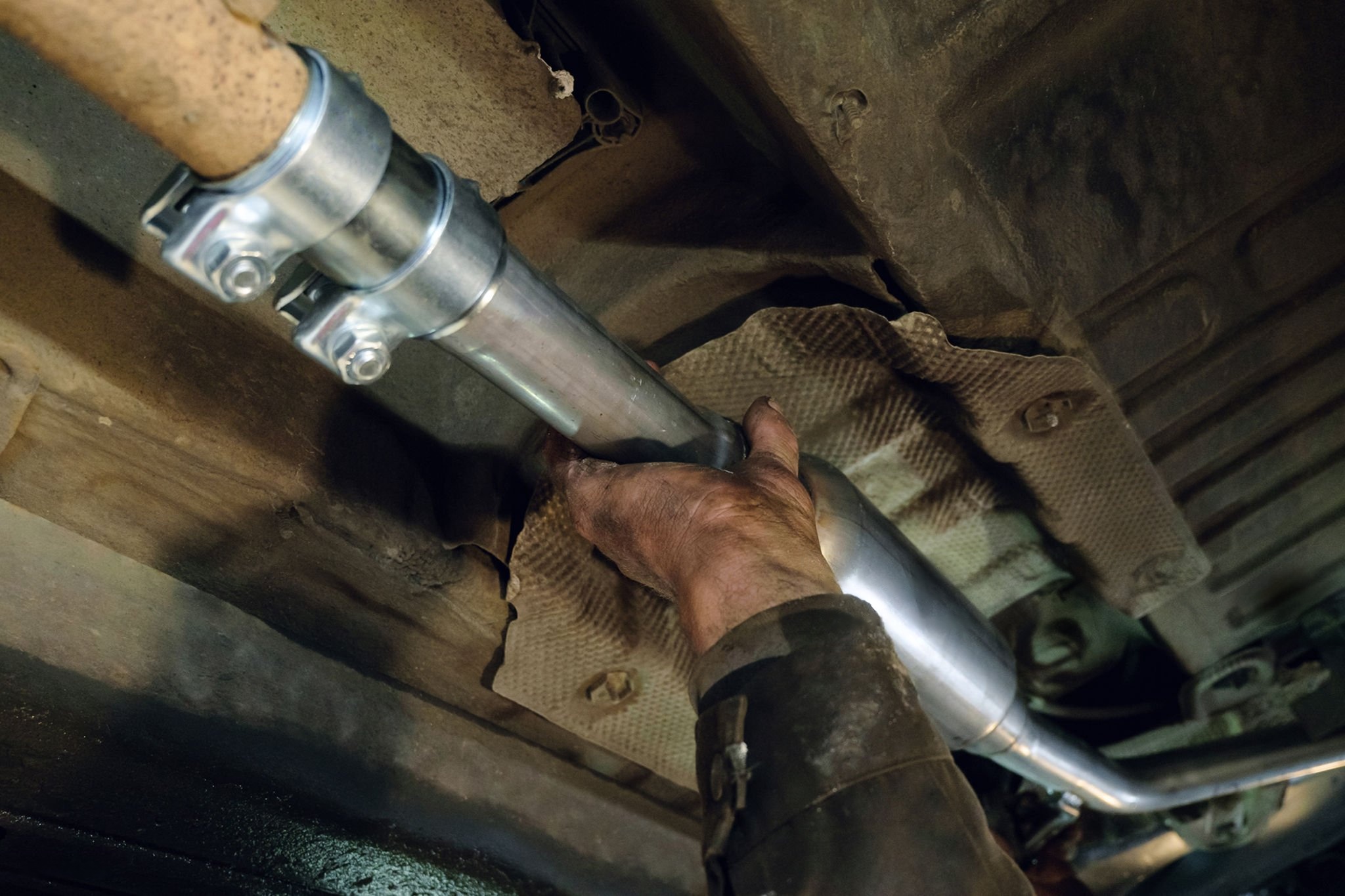
Exhaust Connections at a Glance
Start with what the joint needs to do. The table below identifies the most likely connection type, although final selection still depends on actual dimensions, available space, temperature, vibration, and service requirements.
| What the Joint Must Do | Likely Connection | Why |
| Join two same-size pipes with overlap | Sleeve connector / lap-joint clamp | Simple structure with a defined overlap |
| Join two equal-OD pipe ends without overlap | Butt-joint band clamp | Creates a removable edge-to-edge connection |
| Connect pipes with different diameters | Reducer connector | Provides a controlled size transition |
| Create an accurately positioned bolted joint | Flange and gasket | Controls alignment and sealing position |
| Allow quick removal in limited space | V-band connection | Uses compact matched flanges and one main fastener |
| Allow limited angular movement | Ball-and-socket joint | Accommodates controlled articulation |
| Isolate engine vibration | Flexible exhaust pipe connector | Reduces vibration transferred downstream |
| Absorb defined thermal or axial movement | Exhaust bellows | Designed for movement compensation |
| Split one flow path into two or merge two into one | Y-pipe | Changes exhaust routing |
| Connect the two sides of a dual exhaust system | X-pipe | Creates a crossover between both flow paths |
Main Exhaust Connection Types
Exhaust connections can be divided into three broad groups: rigid pipe connections, flexible connections, and removable fastening connections. The classification is based on the main function of each component rather than its appearance.
Rigid Exhaust Pipe Connections
Rigid connections establish pipe diameter, routing, and mating position. They may be secured with clamps, bolts, or welding, but they are not intended to absorb continuous vibration or significant thermal movement.
1. Sleeve Connector / Exhaust Pipe Coupler
Sleeve connectors are commonly used between straight pipes of the same or closely matched size. Typical applications include middle-pipe repairs, muffler replacement, and general exhaust assembly. The pipe ends slide into the sleeve to create an overlap, after which the joint is clamped or welded.
Proper fit depends on the relationship between the sleeve ID and the mating pipe OD, not simply on the nominal size printed in a catalogue. Excessive clearance can make it difficult for a clamp to load the joint evenly, increasing the risk of leakage or movement. If the fit is too tight, installers may need to expand, grind, or hammer the pipe end, which can distort the joint before it is secured.
A plain tubular sleeve provides the overlap but relies on separate clamps or welding for retention. A wider exhaust pipe sleeve clamp connector may incorporate a broad band, reaction block, reinforcing structure, or pre-attached hardware, allowing it to bridge and fasten the joint at the same time.
Before confirming a specification, check the actual pipe OD, sleeve ID, overall length, insertion depth, slot design, and intended fastening method. For repeat orders, dimensional consistency and roundness usually matter more than a highly polished surface.

2. Reducer Connector
When two exhaust sections have different diameters, an exhaust reducer fitting provides the transition needed to join them. It solves a size mismatch, but it cannot correct major pipe misalignment, an incorrect installation angle, or a damaged pipe end.
Each end should be specified independently. Describing a product only as a “3-inch to 2.5-inch reducer” does not show whether the figures refer to ID or OD, or whether each end fits inside or over the mating pipe.
Overall length and transition geometry also influence fitment. A very short reducer may save space but leave too little straight pipe for a clamp or weld. A longer transition may provide a smoother installation but could interfere with brackets, heat shields, or surrounding components.
The most useful checks are the large- and small-end dimensions, mating direction, overall length, end roundness, and available installation space. General claims about improved exhaust flow should remain secondary to correct fitment and a clean internal transition.

3. Flange and Gasket Connection
Exhaust flanges and gaskets are used where the joint needs accurate positioning, reliable sealing, and later disassembly. Common locations include manifold outlets, catalytic converters, muffler connections, and other bolted sections of the exhaust system.
Compatibility depends on more than the pipe diameter or centre bore. The flange outline, number of bolt holes, hole spacing, hole diameter, thickness, sealing-face design, gasket type, and pipe angle must all match.
Flat gaskets, metal-reinforced gaskets, and spherical sealing rings are designed for different mating surfaces. Similar centre-bore dimensions do not make them interchangeable.
Flatness after welding is another practical concern. Welding a pipe to a thin flange can pull the sealing face out of plane. The bolts may still draw the joint together, but uneven gasket compression can cause leakage after repeated heating and cooling.
For non-standard systems, older vehicles, or custom assemblies, a drawing, physical sample, or measured bolt pattern is generally more reliable than a vehicle description alone.

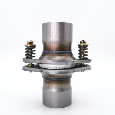
4. Ball-and-Socket Connector
Where limited angular movement is required, a ball-and-socket connection can reduce the bending load placed on a rigid joint. It is often used where engine movement, thermal growth, or assembly variation prevents two exhaust sections from remaining perfectly fixed.
Sealing may come from direct metal-to-metal spherical surfaces or from a shaped gasket held under load by bolts, springs, or a dedicated clamp. Spring-loaded designs can maintain preload while allowing the joint to articulate slightly.
Pipe diameter alone is not enough to confirm compatibility. The ball profile, socket geometry, sealing element, and fastening hardware must work as a matched system.
This connection provides limited angular compensation. It is not a substitute for an exhaust flex pipe where repeated vibration isolation is needed, nor can it absorb the larger axial movement expected from an engineered exhaust bellows.
5. Y-Pipe Connector
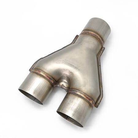
Y-pipes divide one exhaust route into two or merge two routes into one. They are commonly found in single-inlet dual-outlet systems, dual-bank exhaust layouts, and custom installations where two complete pipe routes are not practical.
Fitment depends on more than the inlet and outlet diameters. Branch angle, centreline spacing, overall length, outlet direction, and surrounding clearance all affect whether the part can be integrated into the system.
The internal merge area also deserves attention. Excessive weld intrusion, a narrow opening, or an uneven branch can reduce the usable flow area even when the outside looks clean.
For a standard connection project, correct routing and installation geometry should come first. Symmetry, surface finish, and performance-oriented internal transitions can then be considered where the application requires them.
6. X-Pipe Connector
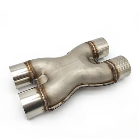
An X-pipe connects the left and right sides of a dual exhaust system through a crossover section. This changes how pressure pulses interact and may affect exhaust tone and flow balance, although the result depends on pipe diameter, crossover position, and the rest of the system.
Before ordering, confirm the dimensions of all four pipe ends, the spacing between both legs, crossover length, included angle, and the space available before nearby mufflers or resonators.
Two X-pipes with a similar exterior can have very different internal openings. A narrow crossover, poor alignment, or heavy weld intrusion may create a restriction, while a well-formed internal section provides a cleaner transition between both flow paths.
An X-pipe should not be presented as a component that guarantees a power increase. For purchasing and assembly, stable end dimensions, clean internal geometry, and reliable integration into the existing exhaust layout are more useful evaluation criteria.
Flexible Exhaust Connections
Relative movement cannot always be eliminated from an exhaust system. Without a flexible section, vibration or thermal growth may be transferred into welds, flanges, catalytic converters, mufflers, and other mounted components.
1. Flexible Exhaust Pipe Connector
A flexible exhaust pipe connector is typically installed close to the engine or another vibration source. Its main purpose is to reduce the fast, repeated movement transmitted to downstream exhaust pipes, catalytic converters, mufflers, and welded joints.
Most exhaust flex pipes contain a corrugated bellows, outer braid, end caps, and connecting pipes. Some designs also include an inner braid or interlock liner. These internal structures affect flexibility, protection, and the behaviour of the gas path, but a thicker appearance or denser braid does not automatically indicate a more durable product.
Key dimensions include the pipe diameter, flexible-body length, total length, nipple dimensions, liner type, braid construction, material, and installation position. Since the internal design is often invisible from the side, end-view photographs, drawings, or physical samples are more useful when confirming the structure.
After installation, the flex pipe should remain close to its natural position. It should not be permanently stretched, compressed, twisted, or pulled sideways to join misaligned pipes. Nor should it replace a bend, hanger, or support.
When the same position suffers repeated cracking, check pipe alignment, engine movement, hangers, and installation preload before simply specifying a thicker or heavier flexible connector.
For a more detailed comparison of diameter, length, liner, braid, and material, see our exhaust flex pipe size, structure and material guide.

2. Exhaust Bellows
Exhaust bellows are used where the system must accommodate defined thermal expansion, axial movement, or vibration from machinery. Although they share a corrugated structure with automotive exhaust flex pipes, their selection is usually more dependent on movement conditions and operating data.
The first point to confirm is whether the main movement is axial, lateral, or angular. Each direction places different demands on the bellows, so the correct structure cannot be selected from appearance or convolution count alone.
Useful starting information includes pipe diameter, installation length, operating temperature, movement direction, and connection method. For higher-temperature or industrial systems, actual operating conditions provide a more reliable basis for selection than a photograph or general product description.
Bellows can only absorb movement within their intended range. They do not replace proper anchors, guides, hangers, or pipe alignment.
More detailed movement and structure considerations are covered in our metal bellows guide.

Removable and Fastening Connections
These connections use mechanical clamping to retain and seal the pipe ends while allowing later disassembly. Their performance depends on the clamp design, pipe-end geometry, and the amount of straight pipe available around the joint.
1. Butt Joint / Band Clamp
A butt-joint band clamp bridges two pipes with the same or nearly the same OD, without one pipe sliding inside the other. A wide band clamp bridges the gap and provides the clamping and sealing area.
This arrangement works well where future removal is required but there is no expanded pipe end or enough room for a long overlap. It should not be confused with a lap-joint clamp, which is designed for one pipe fitting over another.
If the two pipe diameters differ significantly, additional tightening will not produce a reliable seal. Both ends should be round, aligned, and supported, with enough straight length for the band to sit evenly.
Band width, material thickness, bolt grade, reaction-block design, and internal sealing structure are more meaningful than surface polish. The clamp should not be used to pull severely misaligned pipes together or to replace a missing exhaust hanger.

2. V-Band Connection
A V-band connection consists of two matched flanges and a clamp with a V-shaped inner profile. Tightening the main fastener draws the two flange faces together and creates a compact, removable joint.
This structure is often used around turbocharger outlets, downpipes, catalytic converters, and other assemblies where space is limited and repeated access may be required. Compared with a conventional multi-bolt flange, a V-band connection can usually be opened more quickly and does not require long pipe sections to be pulled apart axially.
The clamp and both flanges must be treated as one matched system. Available V-band clamps and flange kits should therefore be specified together rather than selected by pipe diameter alone. Similar pipe diameters do not guarantee compatibility if the flange angle, outside diameter, sealing face, or V-profile differs.
Weld-on V-band flanges still require controlled fabrication during the initial assembly. Alignment and flatness should be checked before final welding rather than relying on the clamp to pull distorted flanges into position.
How to Measure the Correct Exhaust Pipe Connector Size
One of the most common sizing errors is treating nominal pipe size, measured pipe OD, pipe ID, and connector ID as the same dimension. They are not interchangeable.
Before measuring, remove loose rust, burrs, and debris that could affect the reading. Use a round, undamaged section wherever possible, and measure in more than one direction if the pipe may be oval.
The correct measurement depends on the joint structure:
For a slip fit, compare the receiving connector ID with the inserted pipe OD.
For a butt joint, confirm that both pipe ODs are nearly equal.
For a reducer, measure the large and small ends separately.
For a flange, record the bolt pattern, thickness, and sealing profile as well as the centre bore.
For a flexible connector, confirm the pipe diameter, flexible-body length, total length, and end style.
Parameter | What to Measure | Why It Matters |
Pipe OD | Outside diameter of the mating pipe | Controls slip-fit and clamp selection |
Pipe ID | Inside diameter of the pipe | Important when a component fits inside the pipe |
Connector ID | Inside diameter of the receiving connector | Determines clearance over pipe OD |
Overall Length | End-to-end product length | Must fit the available installation space |
Insertion Depth | Length of pipe overlap | Affects stability and sealing area |
Wall Thickness | Pipe or connector wall | Affects strength, ID and forming behavior |
Joint Type | Butt, lap, flange, V-band or flexible | Determines mating geometry and hardware |
Application Position | Manifold, middle pipe, muffler, tail pipe or machinery | Changes heat, vibration and service requirements |
How to Choose Exhaust Connector Materials
Material selection starts with the component, installation position, and service conditions. Sleeves, reducers, flanges, end pipes, bellows, braid, liners, and caps do not necessarily require the same grade.
For rigid exhaust connectors, material affects corrosion resistance, formability, weldability, appearance, cost, and dimensional stability. Flexible connectors and bellows also require materials that can tolerate repeated movement and the heat-affected areas created during welding.
201 Stainless Steel
Grade 201 may be used in selected cost-controlled exhaust flex pipe or connector configurations. The specification should clearly state which parts use this material.
It should not be treated as a direct equivalent to 304 in applications exposed to significant moisture, salt, or other corrosive conditions.
304 Stainless Steel
Grade 304 offers good general corrosion resistance, formability, and weldability. Depending on the product design, it may be used for bellows, braid, sleeves, flanges, caps, or end pipes.
An “all-stainless” or “304 flex pipe” description should still identify whether 304 applies to the complete assembly or only to selected working components.
409 Stainless Steel
Grade 409 is widely used for automotive exhaust tubing, formed end pipes, and rigid exhaust components. It provides a practical balance between exhaust-system performance and material cost.
In flexible assemblies, it is more commonly specified for nipples or other rigid sections than for every component in the product.
Aluminized Steel
Aluminized steel is often used for cost-sensitive exhaust pipes, sleeves, reducers, and general replacement components. Its protective coating supports many standard exhaust applications, but cut edges, welded areas, forming damage, and corrosive exposure can reduce local protection.
Application-Specific Grades
More demanding corrosive, high-temperature, or OEM applications may call for 316L, 321, 439, 441, or another specified material. These grades should not be presented as universal upgrades. The decision should be based on temperature, corrosion exposure, movement, welding requirements, and the project specification.
Using different materials within the same assembly is normal. What matters is whether each component is clearly specified, suitable for its function, and repeatable in future production batches.
Clamp, Flange, or Welding: How to Choose the Fastening Method
Choose the fastening method only after the joint geometry has been confirmed. A clamp cannot turn a butt joint into a lap joint, and it cannot reliably compensate for a large diameter mismatch or badly distorted pipe ends.
Temperature, vibration, service frequency, installation space, and whether the joint may be permanent determine the most practical option.
| Method | Best Fit | Main Benefit | Main Limit |
| Clamp | Serviceable slip-fit or butt joints | Fast installation and later removal | Must match the joint type, diameter, slots, and tightening range |
| Welding | Permanent joints and fabricated assemblies | Creates a compact permanent connection | Harder to service; poor alignment or heat control can create stress |
| Flange + Gasket | Bolted sections requiring accurate location and disassembly | Controls mating position and allows seal replacement | Bolt pattern, sealing faces, gasket, and tightening condition must match |
For detailed differences between U-bolt, lap-joint, butt-joint, V-band, and other clamp structures, refer to the exhaust clamp selection guide.
FAQ
1. What are the most common exhaust connection types used in automotive systems?
Common automotive exhaust connections include sleeve couplers, reducers, flange-and-gasket joints, ball-and-socket joints, V-band assemblies, butt-joint band clamps, and flexible exhaust connectors.
Sleeve and lap-joint arrangements are used for overlapping straight pipes, while reducers join different diameters. Flanges and V-bands provide removable connections with defined mating surfaces. Ball-and-socket joints allow limited angular movement, and exhaust flex pipes help isolate engine vibration.
The right choice depends on the existing pipe-end geometry, available space, movement, and service requirements rather than the connector name alone.
2. What is the difference between a V-band and a conventional bolted exhaust flange?
Both create removable joints, but their geometry and service characteristics differ.
A V-band uses a clamp with a shaped inner profile to draw two matched flanges together. It is compact, usually relies on one main fastener, and works well where repeated access is required in limited space.
A conventional flange uses several bolts and often a separate gasket. It can provide more flexibility in bolt pattern, overall size, and custom interface design.
V-band parts must belong to the same flange-and-clamp profile. Matching pipe diameter alone does not make two V-band systems compatible. Conventional flanges require the bolt pattern, face geometry, thickness, gasket, and welded alignment to match.
3. Is a flange connection more durable than a slip-fit exhaust joint?
Neither is automatically more durable. The better option depends on where and how the joint is used.
A flange provides defined positioning and is often preferred where accurate alignment, gasket sealing, or repeated disassembly is required. It is generally more complex and needs adequate installation space.
A slip-fit connection is simpler and often quicker to install in middle-pipe, muffler, or repair applications. Its performance depends heavily on correct OD-to-ID clearance, overlap, slot design, and clamp selection.
For a standard straight-pipe repair, a correctly sized slip fit may be the more practical choice. Where positioning and controlled disassembly are more important, a flange is usually easier to manage.
4. Where can buyers source consistent exhaust clamps and pipe connectors?
For repeat or custom purchasing, product photographs and nominal sizes are not enough. The supplier should be able to confirm actual OD and ID, butt-joint or lap-joint geometry, flange and clamp compatibility, material allocation, wall thickness, and repeatability between production batches.
YDCT supplies exhaust flex pipes, exhaust bellows, butt-joint and lap-joint clamps, V-band assemblies, sleeve couplers, and related exhaust connection components. Specifications can be reviewed from measured pipe dimensions, drawings, samples, or clear photographs.
For a more accurate review, provide the mating pipe dimensions, joint type, installation position, material requirement, expected quantity, and any available drawing or sample. Packaging, labelling, and specification identification can also be defined for repeat orders.
Conclusion
The correct exhaust pipe connector must match the joint geometry, actual dimensions, installation position, and operating conditions. Identifying whether the connection is a butt joint, lap joint, reducer, flange, V-band, ball joint, or flexible section should come before choosing the material and fastening method.
When the correct structure is still unclear, contact YDCT with the pipe dimensions, installation position, photographs, drawing, or sample. We can help review the main specifications for exhaust flex pipes, bellows, clamps, and related connection components.


About Yueding
YUEDING manufactures stainless steel exhaust flexible connectors, clamps, metal bellows, and selected automotive exhaust components under ISO and IATF quality systems. With in-house production, inspection, and packaging capabilities, we support bulk orders, standard-size inventory, and customized branding for global B2B customers.
Reliable Delivery
Stable production planning, standard-size inventory, and batch shipping support help make delivery more predictable.

Factory Direct
Production, inspection, and packaging are managed in-house, making communication, quality control, and customization more efficient.

Integrated Supply
We supply flex pipes, clamps, metal bellows, and selected exhaust components to support related purchasing needs from one manufacturer.

