T-Bolt V Band Clamp With Flange
 |


Share to:


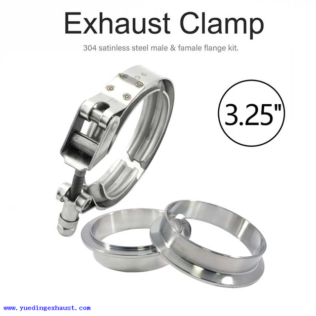
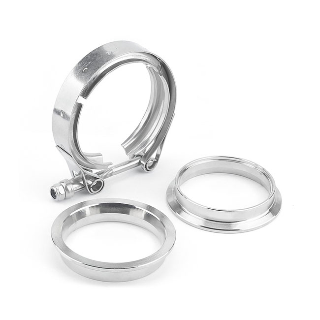
T-bolt V-band clamps are stainless steel clamps used for exhaust, turbocharger, machinery, and pipe flange connections. The V-section profile helps apply 360-degree axial compression around the flange, supporting stable tightening, sealing contact, and easier assembly than traditional multi-bolt flange connections.
Yueding supplies AISI 304 and 316 stainless steel V-band clamps in standard sizes from 1.75" to 6.8" / 44–173 mm. V-profile structures, bolt options, knob options, nut configurations, and packing requirements can be reviewed according to your drawings, samples, flange geometry, working temperature, and bulk order needs.
Yueding supplies AISI 304 and 316 stainless steel V-band clamps in standard sizes from 1.75" to 6.8" / 44–173 mm. V-profile structures, bolt options, knob options, nut configurations, and packing requirements can be reviewed according to your drawings, samples, flange geometry, working temperature, and bulk order needs.
| Band Width | Material Grade | Band | Bridge | Trunnion | Cap | Spring | Bolt | Nut | Suggested Install Torque |
| 19 mm | W2 | AISI SS301 / SS304 | AISI SS301 / SS304 | AISI SS301 / SS304 | AISI SS304 | Zinc Plated Steel | Zinc Plated Steel | Zinc Plated Steel | 9 Nm |
| 19 mm | W4 | AISI SS301 / SS304 | AISI SS301 / SS304 | AISI SS301 / SS304 | AISI SS304 | — | AISI SS304 | AISI SS304 | 9 Nm |
| SAE Size | Inch Range | mm Range | ||
| — | 1 1/4–1 7/16 | 32–37 | ||
| — | 1 3/8–1 9/16 | 35–40 | ||
| — | 1 1/2–1 11/16 | 38–43 | ||
| — | 1 5/8–1 7/8 | 41–46 | ||
| 28 | 1 3/4–2 | 44–52 | ||
| 30 | 1 13/16–2 1/16 | 46–54 | ||
| 34 | 1 15/16–2 1/4 | 50–58 | ||
| 40 | 2 1/8–2 7/16 | 54–62 | ||
| 46 | 2 5/16–2 5/8 | 59–67 | ||
| 52 | 2 1/2–2 13/16 | 64–72 | ||
| 58 | 2 11/16–3 | 69–77 | ||
| 64 | 2 7/8–3 3/16 | 73–81 | ||
| 70 | 3 1/16–3 3/8 | 78–86 | ||
| 76 | 3 1/4–3 9/16 | 83–91 | ||
| 82 | 3 7/16–3 3/4 | 88–96 | ||
| 88 | 3 5/8–3 15/16 | 92–100 | ||
| 94 | 3 13/16–4 1/8 | 97–105 | ||
| 100 | 4–4 5/16 | 102–110 | ||
| 108 | 4 1/4–4 9/16 | 108–116 | ||
| 116 | 4 1/2–4 13/16 | 114–122 | ||
| 124 | 4 3/4–5 1/16 | 121–129 | ||
| 132 | 5–5 5/16 | 127–135 | ||
| 140 | 5 1/4–5 9/16 | 134–142 | ||
| 148 | 5 1/2–5 13/16 | 140–148 | ||
| 156 | 5 3/4–6 1/16 | 146–154 | ||
| 164 | 6–6 5/16 | 153–161 | ||
| 172 | 6 1/4–6 9/16 | 159–167 | ||
| 180 | 6 1/2–6 13/16 | 165–173 | ||
| The size ranges above are for standard V-band clamp reference. Other clamp diameters, band widths, V-profile structures, latch types, and hardware options can be reviewed according to drawings or samples. | ||||
| Nominal Size | Length | Width | Height | Volume | Approx. Unit Weight | |||||
| 1.5" | 12 cm | 1.90 cm | 1.90 cm | 43.32 cm³ | 60 g | |||||
| 1.75" | 14 cm | 1.90 cm | 1.90 cm | 50.54 cm³ | 63 g | |||||
| 2" | 16 cm | 1.90 cm | 1.90 cm | 57.76 cm³ | 66 g | |||||
| 2.25" | 18 cm | 1.90 cm | 1.90 cm | 64.98 cm³ | 67 g | |||||
| 2.36" | 19 cm | 1.90 cm | 1.90 cm | 68.59 cm³ | 68 g | |||||
| 2.5" | 20 cm | 1.90 cm | 1.90 cm | 72.20 cm³ | 70 g | |||||
| 2.75" | 22 cm | 1.90 cm | 1.90 cm | 79.42 cm³ | 73 g | |||||
| 3" | 24 cm | 2.20 cm | 2.20 cm | 116.16 cm³ | 81 g | |||||
| 3.25" | 26 cm | 2.20 cm | 2.20 cm | 125.84 cm³ | 87 g | |||||
| 3.5" | 28 cm | 2.20 cm | 2.20 cm | 135.52 cm³ | 89 g | |||||
| 4" | 32 cm | 2.20 cm | 2.20 cm | 154.88 cm³ | 96 g | |||||
| 4.5" | 36 cm | 2.20 cm | 2.20 cm | 174.24 cm³ | 101 g | |||||
| 5" | 40 cm | 2.20 cm | 2.20 cm | 193.60 cm³ | 106 g | |||||
| 6" | 48 cm | 2.20 cm | 2.20 cm | 232.32 cm³ | 116 g | |||||
| The data above is for regular-size packing and unit weight reference only. Actual packing size and weight may vary depending on clamp structure, band width, material, latch type, order quantity, and customer packaging requirements. | ||||||||||
Latch & Tightening Options for V-Band Clamps

Standard T-Bolt Type
A common V-band clamp structure for stable tightening and regular flange connection. It is suitable for applications where the clamp does not need frequent opening and the main requirement is firm holding and reliable assembly.

Quick Release Type
Used for applications that require easier opening, inspection, maintenance, or repeated disassembly. The quick-release latch helps reduce service time when the clamp needs to be opened and closed more often.

Double-Bolt Type
Designed with two bolt tightening points to help distribute clamping force more evenly. This type is often reviewed for larger diameters, heavier assemblies, or flange connections that need more balanced tightening on both sides.

Worm-Drive Type
Designed with an adjustable worm-drive tightening structure. This type can be considered when the application needs a wider adjustment range, easier diameter control, or a different tightening method from standard T-bolt structures.

Heavy-Duty Type
Built with a stronger tightening structure for applications that require higher clamping force, better vibration resistance, or more stable connection under demanding working conditions. Material, bolt, and nut options should be confirmed based on the actual application.
Hardware Options
we suggest confirming the bolt, nut, and tightening structure together with the clamp drawing or sample before production.

| Bolt Option | Thread Options | Bolt Material & Specification |
| YDB1 | 10-32, 1/4-28, M6 × 1.0, 5/16-24, 3/8-16, 1/2-13 | 4037 alloy steel, heat treated, 125,000–145,000 psi, zinc plated |
| YDB2 | 10-32, 1/4-20, 1/4-28, 5/16-18, 5/16-24, 3/8-16 | 18-8 stainless steel, 302 or 305 |
| YDB3 | 1/4-28, 5/16-24 | 431 / 420 / 410 stainless steel, heat treated, 140,000–160,000 psi |
| YDB4 | 10-32, 1/4-28 | A286 stainless steel, minimum 130,000 psi |
| YDB5 | 1/4-28, M6 × 1.0, M8 × 1.25 | 316 stainless steel |

| Knob Option | Type / Size | Material & Specification |
| YDK1 | Hand-tightening knob, 1 in. long / 25.4 mm | Plastic knob with brass insert |
| YDK2 | Hand-tightening knob, 1.75 in. long / 44.5 mm | Plastic knob with brass insert |
| YDK3 | T-handle, 3 in. long / 76.2 mm | Steel handle, cadmium or zinc plated |

| Nut Option | Nut Material & Locking Specification | Temperature Rating | Self-Locking |
| YDS1 | Steel self-locking nut, nylon insert, zinc plated or other finish options upon review | 250°F / 120°C | Yes |
| YDS2 | All-metal steel self-locking nut, collar or short beam design, zinc plated or other finish options upon review | 550°F / 290°C | Yes |
| YDS3 | All-metal 18-8 stainless steel self-locking nut, collar or short beam design, silver plated | 800°F / 425°C | Yes |
| YDS4 | All-metal 347 stainless steel self-locking nut, collar or short beam design, silver plated | 1200°F / 650°C | Yes |
| YDS5 | 18-8 stainless steel self-locking nut, nylon insert, silver plated | 250°F / 120°C | Yes |
| YDS6 | Stainless steel hex nut, silver plated | 800°F / 425°C | No |
| YDS7 | Steel hex nut, zinc plated | — | No |
V-Profile Options

The six profile options shown here include common variations in profile width, height, wall thickness, and groove angle, helping support different installation spaces, tightening requirements, and flange contact conditions.In addition to these reference profiles, Yueding can review drawing-based V-profile customization for matched assemblies, replacement parts, and project-specific applications. You can send the flange drawing, sample photo, clamp diameter, band width, material requirement, and working conditions, and we will check whether a standard profile can be used or whether a custom section should be developed.