|
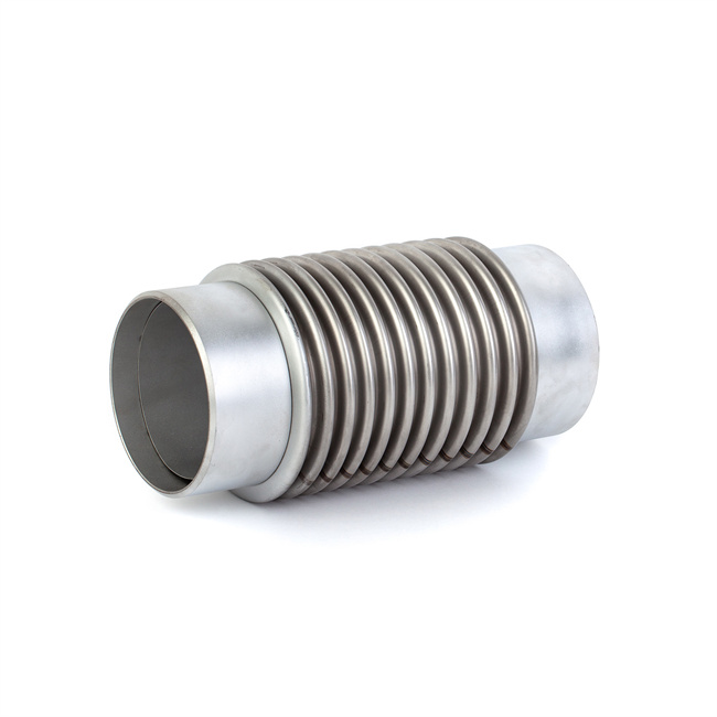


Weld End Exhaust Bellows
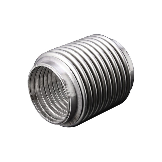
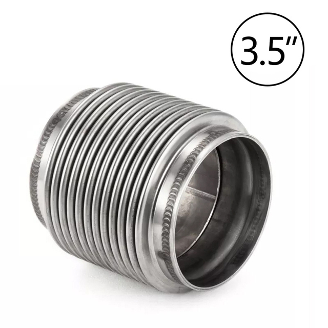
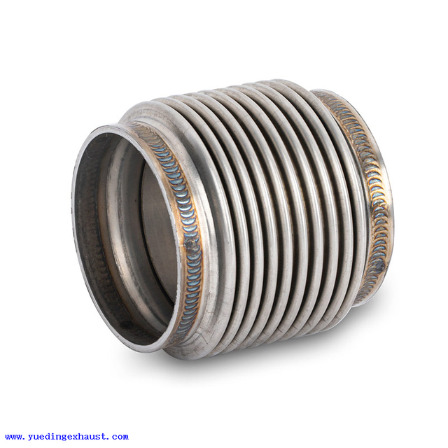
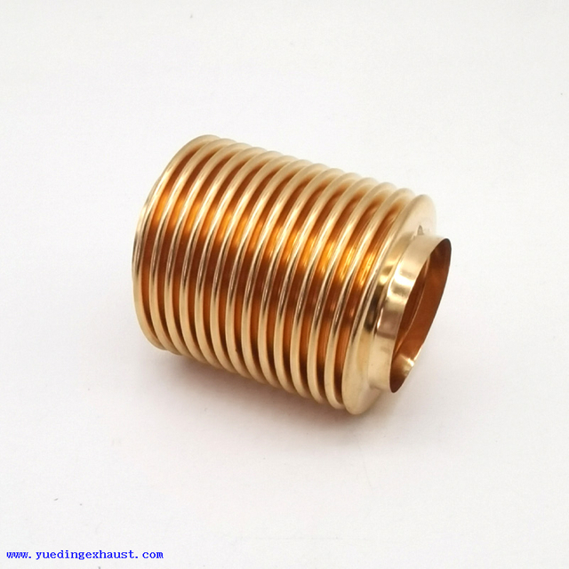
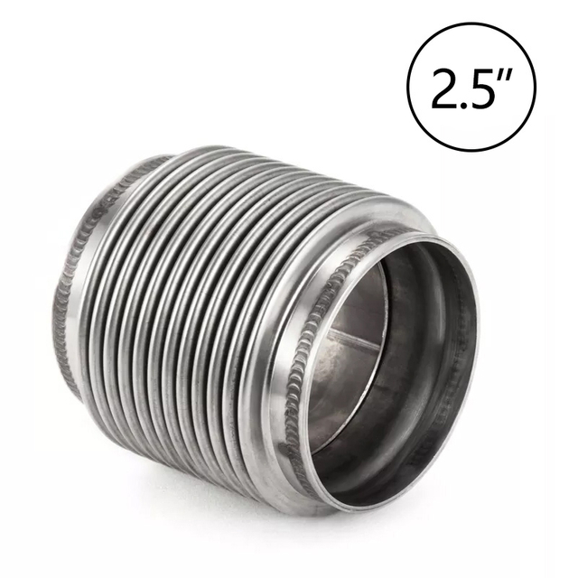
Weld-end exhaust bellows are flexible metal components used to connect exhaust pipe sections while reducing piping stress caused by thermal expansion, mechanical vibration, and limited axial movement. A standard assembly consists of a formed stainless steel bellows with straight pipe ends that can be welded directly into engine, generator, marine, and industrial equipment exhaust systems.
Yueding manufactures weld-end exhaust bellows for bulk orders and customized exhaust system projects. Pipe diameter, overall length, end-pipe dimensions, material grade, and single- or multi-ply bellows construction can be customized from drawings, samples, and confirmed operating conditions. Optional configurations include internal liners and external protective sleeves. We support drawing review, rapid sample development, and OEM/ODM production with competitive pricing. Provide the required dimensions, installation position, and operating conditions so that we can confirm a suitable specification.
Yueding manufactures weld-end exhaust bellows for bulk orders and customized exhaust system projects. Pipe diameter, overall length, end-pipe dimensions, material grade, and single- or multi-ply bellows construction can be customized from drawings, samples, and confirmed operating conditions. Optional configurations include internal liners and external protective sleeves. We support drawing review, rapid sample development, and OEM/ODM production with competitive pricing. Provide the required dimensions, installation position, and operating conditions so that we can confirm a suitable specification.
Product Description

| Specifications | Diameter (DN) | Axial Compensation (mm) | Axial Stiffness (N/mm) | Maximum Radial Size (mm) | Interface Dimension (D × d, mm) | Product Length L (mm) | Pressure Range (MPa) |
| TB100 × □-□ | DN100 | 13–54 | 1323–115 | 238 | Ø108 × 4 | 280–380 | 0.25–2.5 |
| TB150 × □-□ | DN150 | 15–67 | 1910–158 | 289 | Ø159 × 4.5 | 280–380 | 0.25–2.5 |
| TB200 × □-□ | DN200 | 30–101 | 1493–106 | 389 | Ø219 × 6 | 380–520 | 0.25–2.5 |
| TB250 × □-□ | DN250 | 30–124 | 1850–126 | 443 | Ø273 × 8 | 380–520 | 0.25–2.5 |
| TB300 × □-□ | DN300 | 34–111 | 2945–110 | 495 | Ø325 × 8 | 400–600 | 0.25–2.5 |
| TB350 × □-□ | DN350 | 33–117 | 3229–119 | 577 | Ø377 × 8 | 400–600 | 0.25–2.5 |
| TB400 × □-□ | DN400 | 36–122 | 3690–131 | 626 | Ø426 × 8 | 400–600 | 0.25–2.5 |
| TB450 × □-□ | DN450 | 38–125 | 4145–145 | 678 | Ø478 × 8 | 400–600 | 0.25–2.5 |
| TB500 × □-□ | DN500 | 31–125 | 4600–160 | 729 | Ø529 × 8 | 400–600 | 0.25–2.5 |
| TB600 × □-□ | DN600 | 53–156 | 2908–135 | 830 | Ø630 × 10 | 560–850 | 0.25–2.5 |
| TB700 × □-□ | DN700 | 50–158 | 2656–145 | 980 | Ø720 × 10 | 560–850 | 0.25–2.5 |
| TB800 × □-□ | DN800 | 50–159 | 2924–155 | 1080 | Ø820 × 10 | 560–850 | 0.25–2.5 |
| TB900 × □-□ | DN900 | 50–164 | 3205–167 | 1180 | Ø920 × 10 | 560–850 | 0.25–2.5 |
| TB1000 × □-□ | DN1000 | 50–163 | 4104–184 | 1280 | Ø1020 × 10 | 560–850 | 0.25–2.5 |
| TB1100 × □-□ | DN1100 | 32–116 | 4473–263 | 1380 | Ø1120 × 10 | 680–800 | 0.25–1.6 |
| TB1200 × □-□ | DN1200 | 32–116 | 4843–283 | 1480 | Ø1220 × 14 | 680–800 | 0.25–1.6 |
| TB1300 × □-□ | DN1300 | 31–113 | 5215–303 | 1580 | Ø1320 × 14 | 680–800 | 0.25–1.6 |
| TB1400 × □-□ | DN1400 | 31–111 | 5587–323 | 1680 | Ø1420 × 14 | 680–800 | 0.25–1.6 |
| TB1500 × □-□ | DN1500 | 31–116 | 5961–343 | 1780 | Ø1520 × 14 | 680–800 | 0.25–1.6 |
| TB1600 × □-□ | DN1600 | 33–113 | 6242–363 | 1880 | Ø1620 × 14 | 680–800 | 0.25–1.0 |
| TB1700 × □-□ | DN1700 | 33–107 | 6611–383 | 1980 | Ø1720 × 14 | 700–820 | 0.25–1.0 |
| TB1800 × □-□ | DN1800 | 33–106 | 6981–403 | 2080 | Ø1820 × 14 | 700–820 | 0.25–1.0 |
| TB1900 × □-□ | DN1900 | 33–106 | 7351–423 | 2180 | Ø1920 × 14 | 700–820 | 0.25–1.0 |
| TB2000 × □-□ | DN2000 | 36–88 | 5721–708 | 2360 | Ø2020 × 14 | 725–800 | 0.25–1.0 |
Manage Thermal Movement and Vibration
Direct Weld-End Integration
Straight pipe ends allow you to weld the bellows assembly directly into the exhaust line without adding separate flanges, gaskets, or multiple fasteners. The compact structure takes up less installation space and reduces the number of connection parts that need to be matched during assembly.
By confirming the end-pipe OD, wall thickness, length, and edge preparation in advance, you can achieve a cleaner fit with the adjoining pipe and reduce additional cutting, expanding, or adjustment during installation. Proper alignment and welding also help maintain stable sealing and load distribution at the joint.
Bellows Construction Matched to Your Application
You can select a single- or multi-ply bellows according to the pressure, temperature, required movement, and flexibility of the exhaust system. A single-ply structure provides a straightforward construction, while a properly designed multi-ply bellows can offer lower spring stiffness and greater flexibility under comparable total wall thickness and convolution geometry.
An internal liner can be added where the flow path requires guidance or where the bellows should be separated from direct gas impact. An external protective sleeve can help shield the corrugated section from impact and handling damage. Selecting the appropriate structure from the beginning helps you maintain consistent fitment and performance when the same specification is used again.
Product Questions & Answers
What is the difference between single-ply and multi-ply exhaust bellows?
Single-ply bellows use one metal layer and have a relatively simple structure. Multi-ply bellows consist of two or more thinner layers. With similar total wall thickness and convolution geometry, multi-ply construction generally provides lower stiffness, greater flexibility, and lower deformation stress.
Ply construction should be selected according to required movement, operating pressure, temperature, and expected working cycles rather than layer count alone.
What Information Is Needed to Confirm Weld-End Exhaust Bellows Specifications?
Do Weld-End Exhaust Bellows Need an Internal Liner?
What Inspections Are Performed on Exhaust Bellows Before Shipment?