|


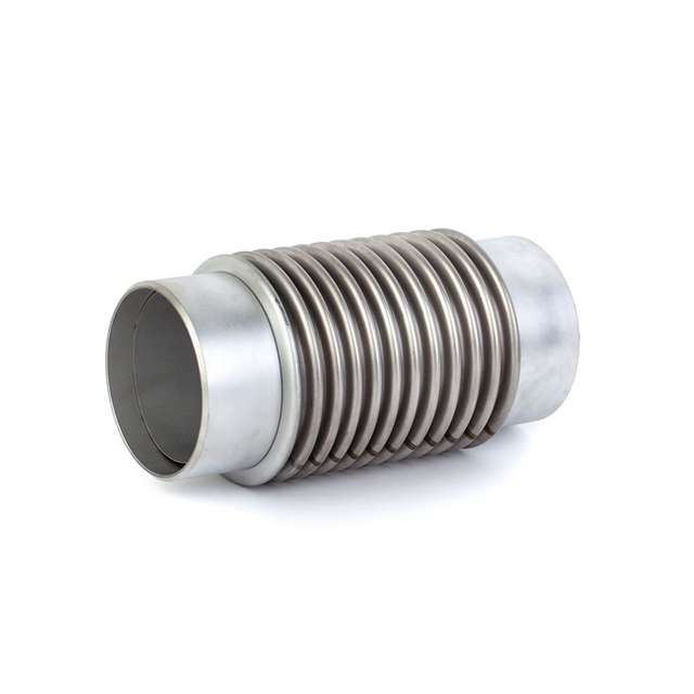
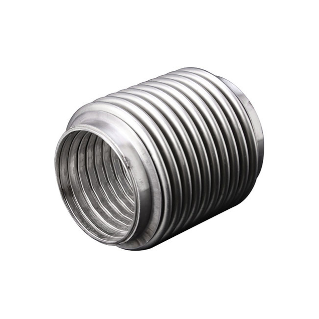
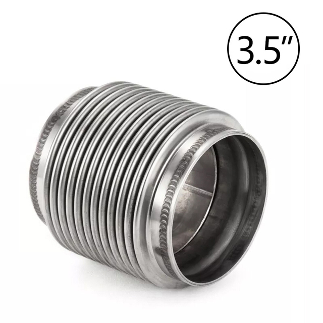
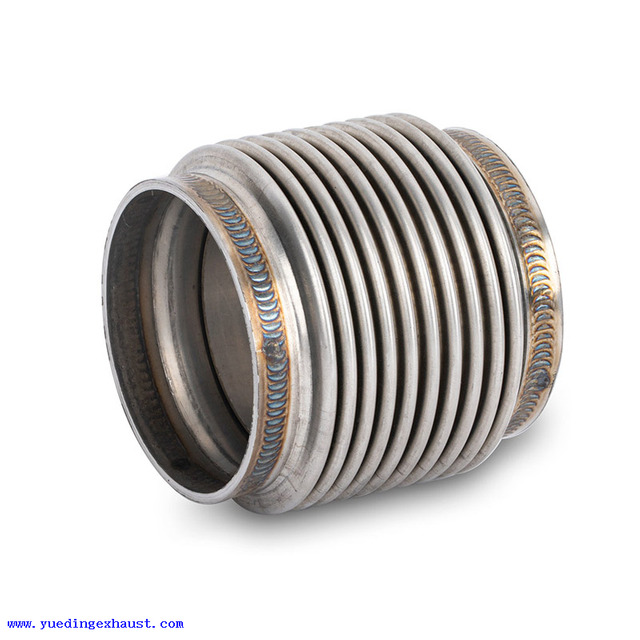
Flanged Exhaust Expansion Joint
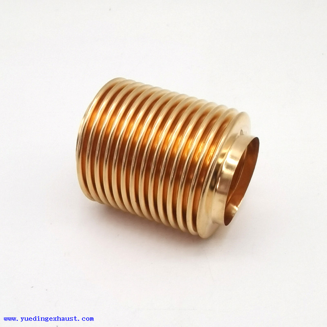
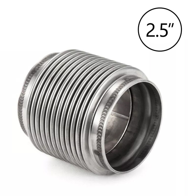
Flanged metal bellows expansion joints connect to pipes or equipment through flanges and are mainly used to accommodate thermal movement caused by temperature changes. Compared with weld-end bellows, flanged connections are easier to install, remove, and maintain, and can be customized according to piping pressure ratings, flange standards, bolt patterns, and equipment interfaces.
Yueding is equipped with product design, CNC machining, and stamping capabilities. Round, square, and custom-shaped flange connections can be produced according to DIN, ASME, JIS, EN, and GB standards or customer drawings. OEM and ODM production is available, and suitable product solutions can be confirmed based on nominal diameter, design pressure, operating temperature, media, required movement, and installation dimensions.
Yueding is equipped with product design, CNC machining, and stamping capabilities. Round, square, and custom-shaped flange connections can be produced according to DIN, ASME, JIS, EN, and GB standards or customer drawings. OEM and ODM production is available, and suitable product solutions can be confirmed based on nominal diameter, design pressure, operating temperature, media, required movement, and installation dimensions.
Product Description

| Specifications | Diameter (DN) | Axial Compensation (mm) | Axial Stiffness (N/mm) | Maximum Radial Size (mm) | Interface Dimension (D × d, mm) | Product Length L (mm) | Pressure Range (MPa) |
| TB100 × □-□ | DN100 | 13–54 | 1323–115 | 238 | Ø108 × 4 | 280–380 | 0.25–2.5 |
| TB150 × □-□ | DN150 | 15–67 | 1910–158 | 289 | Ø159 × 4.5 | 280–380 | 0.25–2.5 |
| TB200 × □-□ | DN200 | 30–101 | 1493–106 | 389 | Ø219 × 6 | 380–520 | 0.25–2.5 |
| TB250 × □-□ | DN250 | 30–124 | 1850–126 | 443 | Ø273 × 8 | 380–520 | 0.25–2.5 |
| TB300 × □-□ | DN300 | 34–111 | 2945–110 | 495 | Ø325 × 8 | 400–600 | 0.25–2.5 |
| TB350 × □-□ | DN350 | 33–117 | 3229–119 | 577 | Ø377 × 8 | 400–600 | 0.25–2.5 |
| TB400 × □-□ | DN400 | 36–122 | 3690–131 | 626 | Ø426 × 8 | 400–600 | 0.25–2.5 |
| TB450 × □-□ | DN450 | 38–125 | 4145–145 | 678 | Ø478 × 8 | 400–600 | 0.25–2.5 |
| TB500 × □-□ | DN500 | 31–125 | 4600–160 | 729 | Ø529 × 8 | 400–600 | 0.25–2.5 |
| TB600 × □-□ | DN600 | 53–156 | 2908–135 | 830 | Ø630 × 10 | 560–850 | 0.25–2.5 |
| TB700 × □-□ | DN700 | 50–158 | 2656–145 | 980 | Ø720 × 10 | 560–850 | 0.25–2.5 |
| TB800 × □-□ | DN800 | 50–159 | 2924–155 | 1080 | Ø820 × 10 | 560–850 | 0.25–2.5 |
| TB900 × □-□ | DN900 | 50–164 | 3205–167 | 1180 | Ø920 × 10 | 560–850 | 0.25–2.5 |
| TB1000 × □-□ | DN1000 | 50–163 | 4104–184 | 1280 | Ø1020 × 10 | 560–850 | 0.25–2.5 |
| TB1100 × □-□ | DN1100 | 32–116 | 4473–263 | 1380 | Ø1120 × 10 | 680–800 | 0.25–1.6 |
| TB1200 × □-□ | DN1200 | 32–116 | 4843–283 | 1480 | Ø1220 × 14 | 680–800 | 0.25–1.6 |
| TB1300 × □-□ | DN1300 | 31–113 | 5215–303 | 1580 | Ø1320 × 14 | 680–800 | 0.25–1.6 |
| TB1400 × □-□ | DN1400 | 31–111 | 5587–323 | 1680 | Ø1420 × 14 | 680–800 | 0.25–1.6 |
| TB1500 × □-□ | DN1500 | 31–116 | 5961–343 | 1780 | Ø1520 × 14 | 680–800 | 0.25–1.6 |
| TB1600 × □-□ | DN1600 | 33–113 | 6242–363 | 1880 | Ø1620 × 14 | 680–800 | 0.25–1.0 |
| TB1700 × □-□ | DN1700 | 33–107 | 6611–383 | 1980 | Ø1720 × 14 | 700–820 | 0.25–1.0 |
| TB1800 × □-□ | DN1800 | 33–106 | 6981–403 | 2080 | Ø1820 × 14 | 700–820 | 0.25–1.0 |
| TB1900 × □-□ | DN1900 | 33–106 | 7351–423 | 2180 | Ø1920 × 14 | 700–820 | 0.25–1.0 |
| TB2000 × □-□ | DN2000 | 36–88 | 5721–708 | 2360 | Ø2020 × 14 | 725–800 | 0.25–1.0 |
Reduce the Impact of Thermal Movement
Stainless steel bellows flex to provide room for piping movement caused by temperature changes, helping reduce stress transferred to flange connections, equipment interfaces, and pipe supports. Axial, lateral, or angular configurations can be selected according to your piping layout, allowing the expansion joint to move in the same direction as the main thermal displacement and reducing connection risks caused by repeated expansion and contraction during long-term operation.
Easier Installation and Maintenance
Flanged ends connect directly to matching pipes or equipment interfaces. Compared with weld-end designs, inspection, maintenance, or replacement can usually be completed without cutting the existing pipeline, helping shorten on-site work and reduce disruption to the overall system. Once flange standard, pressure rating, bolt pattern, and sealing face are matched to your existing interface, dimensional consistency is also easier to maintain during new installation or future replacement.
Balance Movement Capacity and Operating Stability
Single- or multi-ply bellows can be selected according to pressure, temperature, media, required movement, and operating cycles. Under similar total wall thickness and convolution geometry, multi-ply bellows generally have lower stiffness, allowing easier elastic deformation and helping reduce working stress. This makes them suitable for applications involving larger movement or repeated displacement.
Internal liners, external protective covers, tie rods, or limit rods can also be added where required. These components may help improve internal flow conditions, protect the bellows, or control the movement range, allowing the expansion joint to match the actual installation rather than using one fixed configuration for every piping system.
Product Questions & Answers
Why must bolt-hole orientation be confirmed before installing fixed flanges?
Once fixed flanges are welded to the connecting pipes, their bolt-hole orientation usually cannot be rotated. If the hole positions at both ends do not align with the existing pipeline or equipment interfaces, installation may become difficult.
For square flanges, custom-shaped flanges, or projects with specific hole-orientation requirements, the bolt pattern and orientation should be clearly shown on the drawing before production. Where greater on-site alignment flexibility is needed, floating flanges or other suitable connection structures can be evaluated.
Which materials and surface treatments are available for the flanges?
Should temporary support rods between the flanges be removed after delivery?
Does a flanged expansion joint require pre-compression or pre-extension before installation?
Which inspections are normally carried out before shipment?
When are airtightness testing or vacuum leak testing required?
Is an internal liner suitable for every flanged expansion joint?