
How to Choose a Generator Exhaust Flex Pipe
Choosing the wrong generator exhaust flex pipe can cause vibration, stress, leaks, and excessive backpressure. Flexible exhaust tubing for generator systems must absorb vibration, handle thermal movement, and protect the engine from pipe loads. This guide explains how to evaluate support, connections, diameter, movement, and backpressure before choosing the right flex pipe.

How to Choose Flexible Exhaust Tubing for Generator Installations
A good selection process starts with engine data. It then moves through movement, supports, connections, diameter, and backpressure. This sequence prevents one specification from hiding another problem.
Selection Factor | What to Confirm | Common Mistake |
Engine data | Outlet size, flow, temperature, backpressure limit | Choosing by generator kW |
Vibration | Engine movement and mounting system | Making the flex section too rigid |
Thermal movement | Expansion direction and expected travel | Ignoring hot pipe growth |
Support | Silencer, pipe, and riser weight | Hanging weight from the engine |
Connection | Flange, clamp, weld, or tube end | Using flex to fix misalignment |
Diameter | Outlet size, gas flow, system resistance | Using a universal size chart |
Backpressure | Total loss through every component | Checking only the flex pipe |
Start with the Engine Exhaust Data
First, identify the exact engine or generator-set model. Obtain its exhaust outlet size and exhaust flow. You also need exhaust temperature and allowable backpressure. These values matter more than generator output alone. Similar electrical ratings may use different engines. Their turbochargers and exhaust systems can also differ. The engine manufacturer's data should remain the main reference. Cummins also recommends checking the engine-specific backpressure limit before finalizing the exhaust layout.
Identify the Vibration the Flex Pipe Must Isolate
A running engine constantly produces vibration. Starting, stopping, and changing loads also create movement. The flexible section helps keep this movement away from rigid exhaust piping. Consider how the generator itself is mounted. Spring isolators can permit more engine movement. Rigid mounting may produce a different vibration pattern. The goal is not maximum flexibility everywhere. The goal is controlled movement near the engine connection.
Calculate the Direction of Thermal Movement
Exhaust pipes become much hotter during operation. They expand as their temperature rises. Long pipe runs can therefore move several connected components. Do not only ask how much movement occurs. Ask where that movement will travel. Anchors and guides determine the final direction. The flex section may handle axial or lateral movement. Some designs also permit limited angular movement. Its rated movement should match the real installation.
Determine Which Loads the Flex Pipe Will Carry
The flexible connector should not support the complete exhaust system. Heavy silencers and long pipe sections need separate supports. Vertical stacks may require additional structural support. Cummins states that exhaust systems should be self-supported. The engine exhaust outlet should not carry silencer or piping weight. This distinction is important during installation. A flexible pipe handles movement, not structural loading.
Match the Connection to the Exhaust Layout
Check the engine-side connection before choosing the flex pipe. Then confirm the connection used downstream. Common options include flanges, clamps, weld ends, and plain tube ends. A connection should remain sealed during temperature changes. It should also allow practical installation and maintenance. Poor access can turn a simple replacement into major disassembly. The connector should also sit naturally after installation. Avoid pulling the flex pipe into position.
Select the Initial Diameter
Start from the engine exhaust outlet diameter. Do not start from a generic generator-power chart. The outlet provides a practical first reference. Next, review the exhaust gas flow. Higher flow creates greater pressure loss through restrictive sections. Corrugations and internal geometry can also affect resistance. Cummins guidance recommends using piping at least equal to the engine outlet for the stated applications. However, the final diameter still depends on total system backpressure.
Verify the Complete Backpressure
The flex pipe is only one restriction. The silencer, elbows, straight pipe, aftertreatment, and outlet also create losses. You need to evaluate them together. Cummins describes total exhaust backpressure as the combined pressure loss from system components. Its calculation examples include flexible tubing, silencers, elbows, and pipes. The final value must remain below the engine limit. If it does not, the layout needs revision.
How Much Vibration Must the Generator Exhaust Flex Pipe Absorb?
Vibration isolation is one main reason for using flexible tubing. However, the pipe should not move without control. Proper positioning matters as much as flexibility.
Separate Engine Vibration from Pipe Movement
Engine vibration usually creates repeated small movements. Thermal expansion produces slower movement over longer distances. The flexible section may experience both forces. Treating these movements as identical can cause poor selection. A pipe designed for vibration may have limited thermal travel. Another design may handle expansion but transmit more engine vibration. Define each movement before selecting the product.
Position the Flex Pipe Near the Engine Outlet
The flexible connection should normally sit close to the exhaust outlet. This reduces vibration transfer into rigid downstream piping. It also limits external loading at the engine connection. Caterpillar recommends isolating the exhaust pipe from the engine. Its guidance places flexible connections near the engine exhaust outlet. Avoid adding a long rigid section first. It can act like a lever against the engine connection.
Do Not Use Flex Pipe to Fix Major Misalignment
Flexible does not mean infinitely adjustable. The connector should not correct badly positioned rigid pipes. Forced offset creates permanent stress before the engine starts. Correct the pipe supports and geometry first. Then install the flex section near its neutral position. This gives it usable movement during operation. Cummins also warns against using flexible tubing to compensate for incorrect exhaust alignment.
How Thermal Expansion Changes Flex Pipe Selection
Heat changes the geometry of an exhaust system. A cold installation can look perfectly aligned. Once the engine reaches operating temperature, the layout changes.
Estimate Thermal Growth Before Selection
Start by identifying long straight pipe sections. Note their materials and operating temperatures. Longer and hotter sections usually create more total growth. You do not need to guess this movement. Pipe expansion can be calculated from material data. The exhaust temperature should come from engine specifications. This estimate helps define the required travel range. It also guides anchor and support placement.
Match the Flex Pipe to the Movement Direction
Axial movement follows the pipe centerline. Lateral movement occurs across that centerline. Angular movement changes the direction between connected sections. A product may tolerate these movements differently. Check the supplier's rated movement for each direction. Do not rely only on overall flex length. The installed geometry should match the intended movement mode. Otherwise, service life can fall quickly.
Keep Thermal Loads Away from the Turbocharger
Hot rigid pipes can push against fixed points. That force may return toward the turbocharger. This creates bending loads that were never intended. Guides and anchors should direct expansion away from the engine. Expansion joints can then absorb movement at planned locations. Cummins specifically recommends directing exhaust growth away from the generator set. The flexible connector works best inside this controlled system.
How to Choose the Right Exhaust Diameter
Diameter directly affects gas velocity and pressure loss. However, there is no universal generator-kW-to-pipe-size formula. Engine design and exhaust layout change the answer.
Begin with the Engine Outlet Size
Use the engine exhaust outlet as the first sizing reference. Avoid reducing the pipe immediately after the outlet. A smaller section can create unnecessary restriction. Still, matching the outlet does not finish the calculation. A long system may require a larger downstream pipe. Several restrictive components can also change sizing needs. Always follow engine-specific requirements first.
Check Exhaust Flow and Allowable Backpressure
Exhaust flow tells you how much gas must pass through the system. Higher velocity generally increases pressure losses. Tight bends and restrictive silencers add further resistance. This is why two similar generator ratings can need different layouts. Their exhaust flow and backpressure limits may differ. Their silencers may also create different restrictions. Use the actual engine data whenever available.
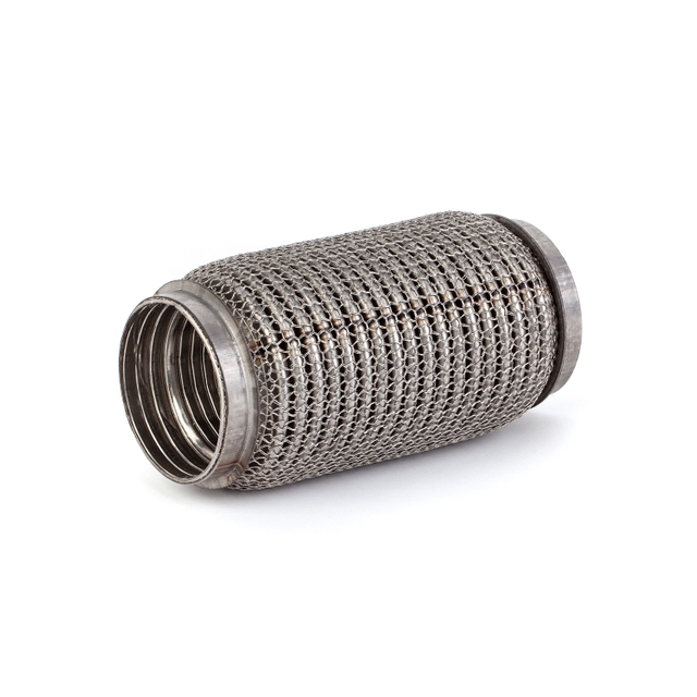
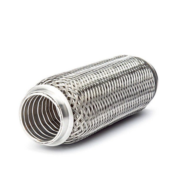
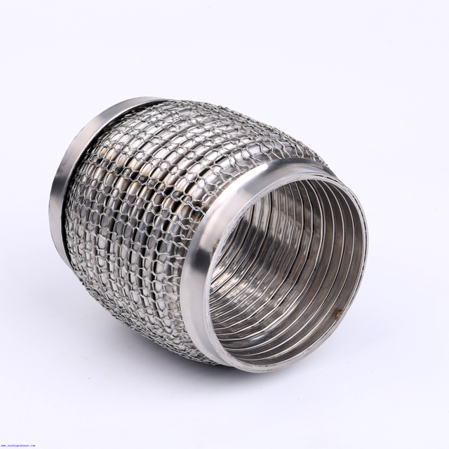
Consider the Flex Pipe's Internal Structure
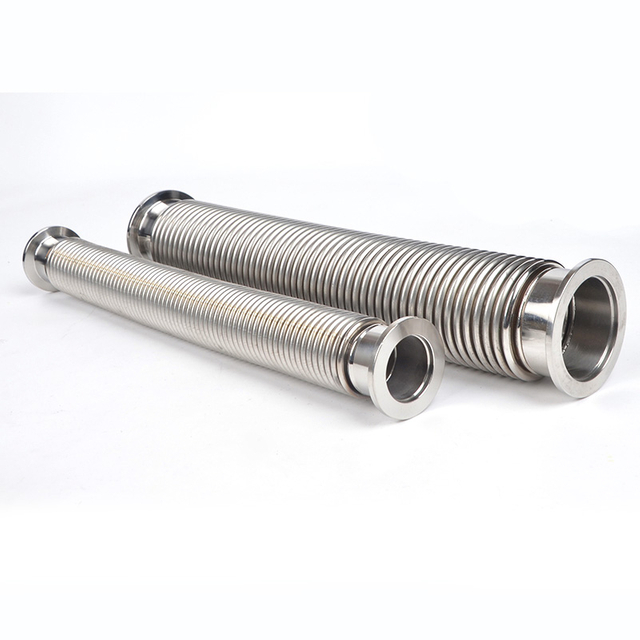
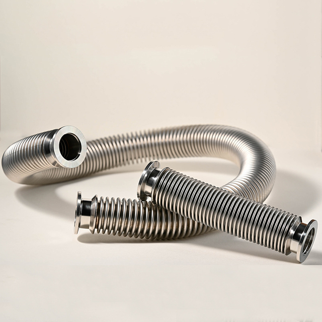
Flexible tubing does not behave exactly like straight pipe. Corrugated walls can increase flow resistance. Some designs use liners to create a smoother gas path. Ask the supplier for pressure-drop information when possible. This becomes more important in high-flow installations. It also matters when the engine allows limited backpressure. A smooth internal path may improve flow performance. However, movement requirements still need equal attention.
Increase Diameter Only for a Reason
Larger pipe can reduce resistance in many systems. Yet oversized piping is not automatically better. It can affect velocity, packaging, weight, and condensate behavior. Cummins also notes possible problems from excessively large exhaust piping in certain installations. Choose diameter from calculated system needs. Do not oversize without an engineering reason.
Choose the Right Flex Pipe Connection
The connection affects sealing, installation, and maintenance. It also influences how forces reach the flexible section. Select it together with the pipe geometry.
Compare Flanged, Welded, and Clamp Connections
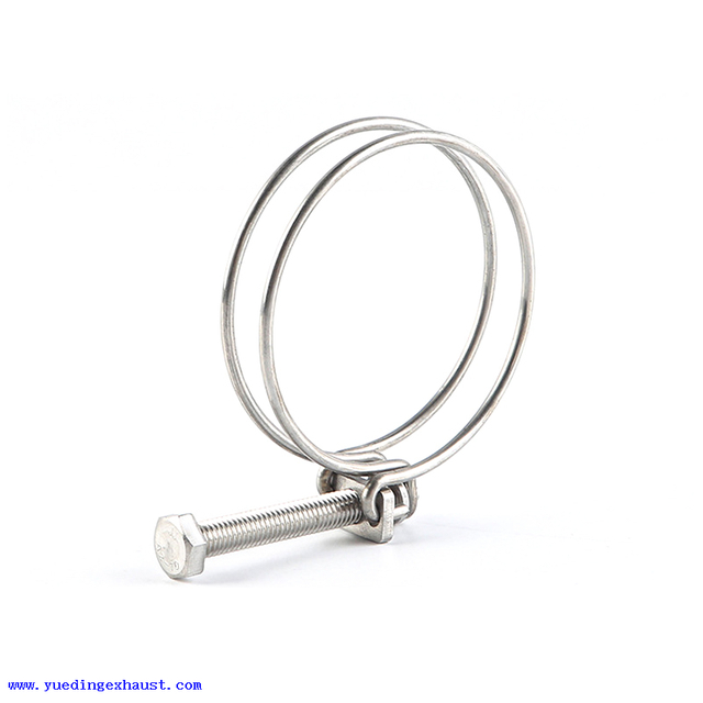
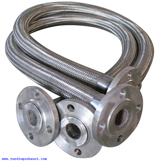
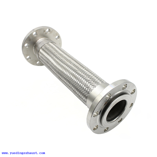
Flanged exhaust flex pipe connections offer reliable positioning and easier removal. Welded ends create permanent joints and compact layouts. Clamp systems can simplify assembly on suitable exhaust designs. Each option has different service needs. Check temperature capability and sealing performance. Also consider available installation space. The engine-side interface often limits your choices. Confirm it before ordering the flex pipe.
Check Alignment Before Final Tightening
Both connection ends should align naturally. Do not use bolts to pull large gaps together. Do not twist the flexible section during assembly. Preloading reduces available movement. It can also create stress around welds or flanges. These loads become worse after heating begins. Correct rigid piping first, then complete the connection.
Plan for Future Maintenance
Flexible sections are service components. They may eventually require inspection or replacement. Leave enough access for removal. Also consider nearby silencers and turbocharger components. A removable flange may be useful in tight generator rooms. A permanent weld may suit other layouts. Maintenance access should be part of initial selection.
Support the Exhaust System Without Loading the Flex Pipe
Support design often determines whether the flexible section works correctly. A good flex pipe cannot compensate for poor supports. The complete exhaust weight needs a separate load path.
Support Silencers and Rigid Pipes Independently
Silencers can place large loads on exhaust connections. Long steel pipes add more weight. Neither should hang from the flexible connector. Use structural hangers or suitable floor supports. They should carry the static exhaust weight. The engine connection should remain free from those loads. This principle protects the manifold and turbocharger.
Use Anchors and Guides to Control Movement
Supports carry weight, while guides control direction. Anchors create fixed points in the system. Each component serves a different purpose. Good placement sends thermal growth toward expansion sections. Poor placement can force movement toward the engine. It may also bend the flex connector sideways. Cummins recommends anchors and guides to manage thermal growth.
Inspect the System Hot and Cold
Check the flex section before starting the engine. Record its cold position if needed. Then inspect it after reaching operating temperature. Look for excessive compression or extension. Also check lateral offset and nearby support movement. The hot position often reveals problems hidden during installation. This inspection is especially useful after commissioning.
Verify Backpressure Before Final Approval
Backpressure is the final system-level check. It confirms whether the selected components work together. A correctly installed flex pipe can still be part of an overly restrictive system.
Calculate the Complete Exhaust Path
Begin at the engine outlet. Continue through every flexible section, elbow, silencer, pipe run, and exhaust accessory. Each component adds some resistance. Longer pipes generally add more pressure loss. Tight bends can increase it further. Silencers can become major restrictions at high gas flow. Do not calculate only the flexible tubing.
Compare the Result with the Engine Limit
The engine manufacturer defines the allowable exhaust backpressure. This value is not universal. It can vary among engine families and operating configurations. Excessive backpressure can reduce engine performance. It may also raise exhaust temperature and affect durability. Cummins specifically requires total backpressure to remain within model limits. Use the exact datasheet whenever possible.
Reduce Restriction if Backpressure Is Too High
Start by locating the largest pressure losses. A restrictive silencer may be more important than straight pipe. Several small elbows may also create meaningful resistance.
Possible changes include:
Increase pipe diameter where engineering permits.
Reduce unnecessary elbows and sharp turns.
Use longer-radius bends when practical.
Shorten excessive exhaust runs.
Select a lower-restriction silencer.
Review the flexible connector pressure drop.
Make one change at a time. Then recalculate the complete exhaust path.
Verify Backpressure During Commissioning
A calculation predicts expected system behavior. Field measurement confirms the installed result. This is useful for long or complex exhaust layouts. Cummins recommends measuring engine exhaust backpressure during commissioning under the required operating condition. Its application guidance references full-load verification for the discussed systems. Measurement can reveal unexpected installation restrictions. It also provides a useful commissioning record.
Conclusion
Choosing flexible exhaust tubing for generator systems requires a complete review of engine data, vibration, thermal movement, and support design. Connections, pipe diameter, exhaust flow, and total backpressure must also stay within the engine manufacturer’s operating limits. Buyers should provide engine data, layout details, movement requirements, and connection information before confirming the final specification. Zhejiang Yueding Corrugated Tube Co., Ltd. provides flexible exhaust solutions that support reliable movement control, secure connections, and demanding generator applications.
FAQ
Q: What is flexible exhaust tubing for generator systems?
A: Flexible exhaust tubing for generator systems absorbs engine vibration and thermal movement. It also helps reduce stress on the manifold, turbocharger, and rigid exhaust piping.
Q: How do I size flexible exhaust tubing for generator use?
A: Size flexible exhaust tubing for generator use by checking outlet diameter, exhaust flow, temperature, and allowable backpressure. Do not select diameter from generator power alone.
Q: Why does flexible exhaust tubing for generator installation need support?
A: Flexible exhaust tubing for generator systems should not carry silencer or pipe weight. Independent supports help prevent sagging, joint stress, and premature flex-pipe failure.
Q: What causes high generator exhaust backpressure?
A: High generator exhaust backpressure can result from undersized pipes, restrictive silencers, long runs, sharp bends, or excessive fittings. The complete exhaust path should be checked.
Q: How much does a generator exhaust flex pipe cost?
A: Generator exhaust flex pipe cost depends on diameter, length, stainless steel grade, flex construction, connection type, and customization requirements.






About Yueding
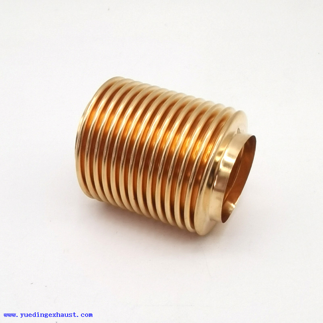
YUEDING manufactures stainless steel exhaust flexible connectors, clamps, metal bellows, and selected automotive exhaust components under ISO and IATF quality systems. With in-house production, inspection, and packaging capabilities, we support bulk orders, standard-size inventory, and customized branding for global B2B customers.
Reliable Delivery
Stable production planning, standard-size inventory, and batch shipping support help make delivery more predictable.

Factory Direct
Production, inspection, and packaging are managed in-house, making communication, quality control, and customization more efficient.

Integrated Supply
We supply flex pipes, clamps, metal bellows, and selected exhaust components to support related purchasing needs from one manufacturer.

